
Looking for digital files? Check out the shop HERE.
One of the reasons I got into 3D design in the first place is that I’m so frequently annoyed by the engineering approaches taken by kits and aftermarket products. We’ve all been there, right? Resin cockpits that don’t come anywhere close to fitting. Beautiful casts and prints that, after you get their pour stubs removed, have no engineering cleverness to offer beyond a butt join. Tracks and wheels that don’t fit. Or tracks that you need Ant-Man’s help to assemble.
What can I say? Little things tend to annoy me when bigger ones don’t. Apparently it’s an ADHD trait.
But yeah, it informs how I approach everything I design. Detail matters. Accuracy matters. Texture matters. But the thing that matters to more more than all the others?
Engineering and go-togetherness.
That’s why I tackled 1/16 Sherman tracks last year. I really dislike trap-style tracks, like these in Classy Hobby’s 1/16 Stuart:

Maddeningly, they also seem to be what the industry overall has settled on when it comes to this style of track in general.
So I designed my own tracks, using full-length track pins that snap into the end connectors, and no split-pad silliness.

From 1/16 to 1/35
Since the first day I released the 1/16 tracks, I’ve been fielding questions about scaling them down to 1/35. And yeah, mathematically it’s entirely possible. But what works very well in 1/16 is a whole different ballgame in 35th.
Strength is a huge factor. Full-width pins with diameters approaching 2mm are much stronger than ones that are under 1mm. And the end connectors in 16th are big enough that they can withstand having hollowed out openings to accept those pins. In 35th, they become very fragile.
The other factor: size. 1/35 VVSS tracks are fucking small. Inserting track pins into end connectors is really tricky when those end connectors are too small to hold easily, and when their shape naturally resists tweezers.
I’ve built tracks that use that approach. And they’re punishing.


Remember what I was saying about engineering and go-togetherness? Yeah.
And those are some of the better Sherman tracks I’ve encountered!
So here’s the thing. If I’m going to do 1/35 tracks, they have to be the tracks that I would want, and that I wouldn’t hate putting together.
Change 1 – Hole Embiggening
I opted to start with T54E1s for two pretty simple reasons. First, Tamiya’s release of the M36. Second, as steel tracks, there’s no rubber texture that needs redoing for 1/35 scale. So it was generally possible to take the 1/16 pads and scale them down.
But not entirely.
I enlarged the pad holes as much as I could possibly get away with. Push it too far, and the pads themselves start losing structural integrity.

Ultimately, I got them to just under 1mm (0.997 if you want to get picky).
Change 2 – Pinned End Connectors
The end connector problem stymied me for a good while. Full width pins set up a situation with too many, too tiny, too fragile parts to manage comfortably.
It’d be so much easier if the pins were already inserted into the end connectors.
Which is what I did. Except instead of full-width, I went with shorter pins (demi-pins?).
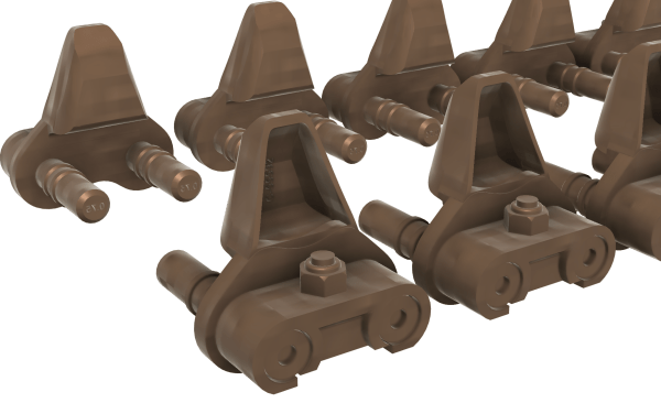
Change 3 – Ruffles and Track Pins Have Ridges
Pins by themselves won’t hold tracks together. They need some kind of retaining element to help keep them in place.
Enter two small ridges, with corresponding spaces inside the tracks for the pins to “lock” into.


One catch to these connectors? To work as intended, they require using a resin with some give. Not even a ton. It just can’t be brittle-ass resin. I’ve had excellent results with Phrozen Aqua-Gray 8K.
Another catch? Tolerances are very tight, and slight differences in print settings, resin used, phase of the moon, and so on can make the difference between a perfect fit, or the pins just not working. So I included a range of pin diameters that should cover most possibilities.
Change 4 – Improved Geometry
This one doesn’t apply to the T54E1s. They were designed separately from the rubber pads and so don’t suffer the same “original sin”.
No, the tracks didn’t eat apples. When I first started sketching them out, I did them as inner and outer pad halves. Mainly out of laziness – the inner faces of T41s, T51s, T48s, and WE210s are essentially identical. So build one half, and then build the other half.
But between lofts, fillets, curves, and my much less disciplined Fusioning when I was originally working on them, the halves have a variety of geometry issues that complicate downstream steps, from enlarging the pad holes to taking the pads into Blender for texturing.
So rather than deal with that hassle, I’m just rebuilding the rubber pads in 35th. Apart from maybe the T48s, they’re rather simple in their design.
Addition – End Connector Holder
Back to 1/35 end connectors being ridiculously small and tweezer-averse, I thought that some kind of holder would be a good idea.
So I’m designing one.
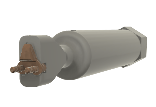
I’ve tested a few prototypes so far and they work really well. A key is the ability to set it down, “reload” it, and pick it back up again one-handed. Right now I’m playing with a recessed spot in the base for a magnet, or using some kind of pin that can be placed into a socket that stays on the bench.
Stay tuned on this one!
Interested in the 1/35 T54E1 Workable Tracks?

Snag them in the shop HERE.
Interesting stuff.
The tracks above that you don’t hate… Kaizen?
Brett G
Yep